Ray Tracing Implementation
Table of Contents
Introduction
In order to produce Ray Traced images, we follow the basic ray tracing algorithm, as follows:
for(each pixel (sample) on the viewing area)
{
   for(each primitive in the world model)
   {
      if(ray-pixel intersection)
      {
          select the frontmost intersection;
          recursively trace the relection and refraction rays;
          calculate color;
      }
   }
}
Sampling
Unfortunately, computers are not able to accurately store real world, continuous data.
Computers are discrete systems, having to represent everything digitally, i.e. as a string of
0's and 1's. In the context of computer graphics, images can be represented digitally as a 2D
grid of dots, called pixels. Each pixel has a color value assignable to it. The proces of looking
at the model, and calculating a color for every pixel position in the camera view is called
Sampling.
The entire process of sampling can be thought of in the following four steps:
- Continuous 2D Signal - computer model which is defined at all points
- Sampling - Measuring rays
- Discrete 2D Image - Collection of all ray-color data
- Continuous 2D Image - an apporoximation, caused by averaging the color data for all the rays in a given pixel)
Different techniques are used for sampling to attempt to provide as accurate as representation as possible
for a world which cannot be completely represented visually by a discrete computer. In other words,
different sampling techniques are used to try to ensure that the model created in step 4 from the discrete
date in step 3 closely resembles a real world view of the model described in step1.
Regular Sampling
The basic form of sampling, regular sampling, involves a fixed number of rays for each pixel. Each pixel
has a constant position in the pixel. For example, a common example of regular sampling is to sample each
pixel four times, once at each corner of the pixel, and once in the center of the pixel. Through ray
tracing, the color of each of the rays can be calculated, and then a final color for the whole pixel
can be calculated for the whole pixel. It should be noted that each pixel can only have one color
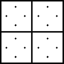
for the whole pixel. The following is an image of regular sampling. Each large square represents a
pixel, and each dot represents a sample. In this case, four samples are taken for each pixel, and they
form a diamond pattern around the center of the pixel. Note that the sampling pattern for each pixel
remains the same, the defining characteristic of regular sampling.
Ray-Surface Intersection Routines
As shown in the pseudo-code above, one of the main aspects of the Ray Tracing algorithm is the ability to test
for the intersection of a primitive and a ray. A primitive is any object that exists in the world. Simple
examples of primitives include spheres and polygons. A collection of polygons are usually connected along
their edges to form more complicated objects. For example, a model of a human head might be made up of
thousands of little trianges which are connected in a way that closely approximates the outer surface of
a human head.
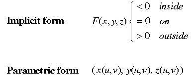
The first step in calculating Ray-Surface Intersection is to obtain a mathematical model for the image.
The image can be defined in two ways as follows. [These two images are re-produced, with permission, from the
Stanford Computer Graphics Lab Web Site @ http://graphics.stanford.edu. Reproduction is prohibited.]
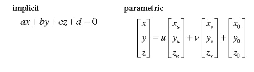
For example, an infinite plane can be defined in both of these ways as follows.
Once we have a mathematical model of every primitive in the scene, we must test each primitive for intersection
with each ray that we are tracing. All these calculations, which must be done recursively until the rays end
cause ray tracing to be a very computationally intensive process.
These intersection problems can be solved algebraically, using a parametric representation of the primitive
and the ray. The solution is not only whether the two intersect, but also, if there is an intersection, the
exact co-ordinates of the intersection. The ray-tracer can then use information about that point on the model
to calculate the appropriate color that that object contributes to the ray.
Precision problems - The self shadowing problem
Due to precision problems inherent to floating point arithmatic, the intersection point that is calculated
can actually lie under the surface of the of sphere. If this happens, when the ray is recursively traced,
it immediately hits itself, causing the unxepected result that the object lies in a shadow created by itself.
Because of this phenomenon, dark splotches can appear on a surface for apparently no reason.

There are methods available to avoid this incorrect shadowing.
- Because the last intersection point of any sphere is known, we can pass a boolean flag
to the ray tracing function telling it is the ray about to be calculated originates from a surface
of a primitive.
- More simply, we can assume that all rays starting within a certain tolerance (for example 0.00001 inches)
of the surface of a primitive actually lie on that surface. This number must be lower for extremely small,
intricate models.
- One can take the given intersection point and use it as the origin for a ray which continues in the
same direction as the calculated ray. In this way, we can find a more accurate intersection point, that
will not be misinterpreted as underneath the surface of an object. This method must still be used in
conjunction with a tolerance factor, but it does allow the progam to be certain that the final calculated
point of intersection lies within a certain distance of the actual point.
- The ray tracer can also move new rays it generates to the appropriate side of the sphere. By following
the normal to the surface, one can move the origin of a new ray to the appropriate side of the surface
(the inside for refraction rays, the outside for reflection rays)
Color Calculation
Once the raytacer determines which primitives intersect the ray, the color of that ray, and its corresponding
pixel, must be computed. On the basis of the materials of the objects that are intersected, one can calculate
the colors that they reflect, and the colors that they absorb. These values are added together for all the
objects that the ray intersects, and the total color is calculated. Objects which are farther away from the eye,
or camera have a lesser effect on the final color than due objects closer to the camera/eye.

Table of Contents